Dimensions - Adding dimensions to your floor plans
Every construction plan and generally every drawing of floor plans, floors and buildings will usually have to be provided with dimensions.
Visual Building software therefore contains all the tools and options to meet every requirement and to draw in the necessary dimensions.
The handling of the dimensions differs in detail and according to the use case.
Standards and specifications sometimes vary from country to country and even according to local requirements.
Since Visual Building is sold and used internationally, we have designed all functions in such a way that you always get the desired and professional result.
More Topics
- Navigation in 2D / 3D
- Create Floor Plans
- Windows and doors
- Insert stairs
- Copy Floors
- Roof Construction
- Building Plans
- Section views
- Elevation views
- 3D Floor Plans
- Become a 3D Architect
- Loft conversion
- Fire Escape Plans
- 2D Symbols
- House Plan Layout
- 3D Constructions
- Home Design Software
- Using 3D Objects
- Using Textures
- Material properties
- 3D Visualization
- Timber frame
Automatic dimensioning of floor plans
Visual Building has automatic dimensioning tools in two variants. On the one hand, you can create an automatic dimensioning suggestion for the current layer, e.g. for the Ground Floor - Floor Plan. This layer must be set as active element in the 2D view you are working in. Visual Building first checks whether the active layer contains walls that form a building outline.
If not, you will receive a corresponding message.
Then the software searches each side of the building and analyzes the floor plan as well as elements such as windows and doors. Automatic dimensioning is then generated separately for each side.
Alternatively, there is a tool to manually generate a dimensioning for just one wall. The automatic dimensions for each building side or wall each form a unit and have their own dialog. They can also be separated into individual dimension lines via the context menu, which can then be edited in detail or deleted.
The video below shows both examples and some of the editing options. Please refer to the manual for more details.
Inserting dimensions manually
In addition to automatic dimensioning, there are tools to insert individual dimension lines.
- Single dimensions
- Automatic multiple dimensions
- Multiple dimensioning via n-points
The multiple dimensioning tool automatically creates dimension chains that also list the windows and doors with the required heights.
This dimension automatically recognizes the walls, windows and doors below it and includes them in the dimension chain.
It can happen that you cannot find a correct position for the automatic dimensioning tool in your floor plan, e.g. if you have to pick doors or windows in your floor plan, which you do not want to appear in your dimension chain.
In this case, use multiple dimensioning via n-points. With this variant, you "pick" the dimensions from the floor plan at any point and in this way assemble a dimension chain.
When inserting dimensions, it is important that you determine the dimension points correctly with your mouse, i.e. zoom in as closely as possible. And if necessary, hold down the CTRL key while dragging a dimension line in order to activate the internal angular grid and generate clean vertical or horizontal measurements.
Slightly incorrectly inserted dimensions or dimension chains would of course also show deviating values.
The following video shows simple examples.
Dimensions of windows and doors
For windows and doors there is an additional option of generating axis dimensions. This is done via the window and door properties dialog. These settings can also be transferred to the other elements in your project with the "Transfer properties..." function, so that you do not have to touch each door or window individually.
Dimensions in sections and elevations, height above sea level
In addition to the normal dimension lines and dimension chains, there are two variants of so-called height marks for height information in sections and elevation views, with a filled black representation for dimensions of the raw construction and a white version for the finished construction. These are only graphic differences. When inserting the height dimensions, you determine where you want to take the measurement and you would also have to decide for yourself which representation to choose.
Some plans need level information relative to the height above sea level instead of the dimensions related to the building level. You can activate this in our height dimension properties dialog and the software will convert the values accordingly. You determine the base value for the height above sea level in our terrain property dialog on the environment layer. But that is only an internal value. The terrain should not and will not become several hundred meters high.
Some plans need level information relative to the height above sea level instead of the dimensions related to the building level. You can activate this in our height dimension properties dialog and the software will convert the values accordingly. You determine the base value for the height above sea level in our terrain property dialog on the environment layer. But that is only an internal value. The terrain should not and will not become several hundred meters high.
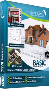
Visual Building Basic

Has been developed as an easy to use design and visualisation tool for self builder,extentions..
£60.00
List price
List price
£39.00
Special online offer
Special online offer
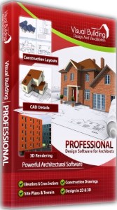
Visual Building PRO

Used by all user groups specifically to create professional plans...
£120.00
List price
List price
£99.00
Special online offer
Special online offer
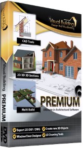
Visual Building Premium

Our most powerful design and visualisation tool specifically created for ...
£180.00
List price
List price
£149.00
Special online offer
Special online offer


