Roof construction in Visual Building
Roofs are always handled as a one element in Visual Building, so they do not initially consist of individual parts.
So as a first step you only insert a contour, a polygon for example. Along this contour Visual Building creates a roof side for each polygon segment. Roof sides and their properties can then be edited and changed in every detail in our Roof editor dialog.
A special highlight of the dialog is the 3D preview window, in which you can select and change roof sides by clicking directly on it. The preview will be recalculated with every change you make. When the roof design is finished, it is inserted into the project by leaving the dialog by clicking on OK.
Roofs automatically cut other construction components such as walls, floors, ceilings and columns. So you do not have to worry about the height and shape of walls. All this happens automatically.
More topics
Create the roof contour
First, you should consider in which floor the roof should be inserted. Usually this happens on a upper floor, but in principle it is arbitrary.
It depends on the structure of the building. In a three floor building with ground floor, first upper floor and attic, you should insert the roof on the upper floor for reasons of later 2D presentation and for the determination of height contour lines and surfaces.
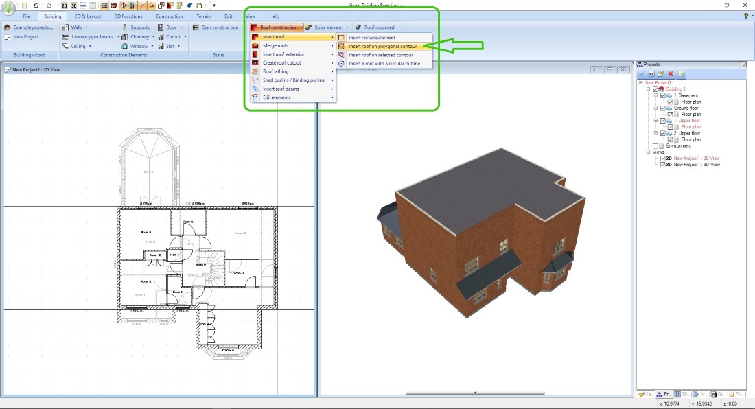
For inserting the roof contour, there are three insertion options available. Rectangular, polygonal and automatic contour recognition. We will concentrate on the polygonal variant in this example.
It depends on the structure of the building. In a three floor building with ground floor, first upper floor and attic, you should insert the roof on the upper floor for reasons of later 2D presentation and for the determination of height contour lines and surfaces.
For inserting the roof contour, there are three insertion options available. Rectangular, polygonal and automatic contour recognition. We will concentrate on the polygonal variant in this example.
After starting the Roof input tool, insert the polygon points of your required roof onto your plan. These are usually the corners of the outer walls, but they do not have to be. You can also place a roof polygon point elsewhere if the roof does not follow your outer building contour but, for example, covers a porch.
In such a case, you should first mark the roof corners with 2D guidelines, to get a clean shape of the roof. It could become a problem, if opposite roof sides are not exactly parallel.
Once the contour is completed, finish the process with ENTER on the keyboard or via the context menu. The roof dialog opens automatically.
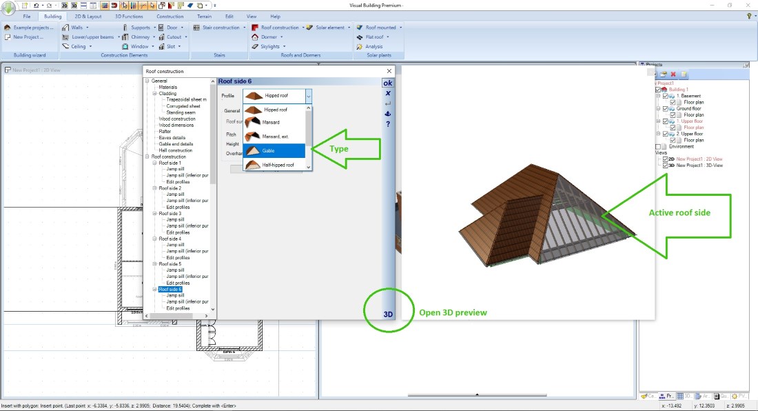
Using the roof construction dialog
First, open the 3D preview and edit the roof sides, the settings you typically have to edit are roof side - type, hipped, gable, etc. and the properties for roof pitch and roof overhang.
Take advantage of the ability to transfer properties of one roof sides to others, it makes editing your roof much faster.
Take advantage of the ability to transfer properties of one roof sides to others, it makes editing your roof much faster.
In the 3D preview window, you can see at any time how the finished roof will look like. Special roof shapes such as sloping roofs (lean-to roofs) are created in the same way, for example by defining three roof sides as a gable and the remaining roof side becomes the sloping roof.
By clicking on OK you insert the roof in your project. You can change all settings again in the roof dialog at any time later if necessary.
By clicking on OK you insert the roof in your project. You can change all settings again in the roof dialog at any time later if necessary.
Determine and change the height of the roof
Often all roof sides have the same height, but it does not have to be that way.
In the roof dialog, you can assign each roof side its own height.
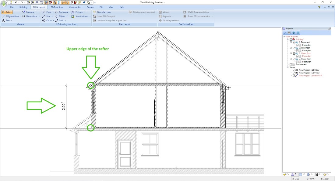
In general, the height displayed in the dialog is measured along the roof contour to the top of the rafters. This value is relative to the floor level in which you inserted the roof.
The screenshot on the right shows where Visual Building takes this value.
The easiest way to measure the correct height is to use a section view. Create such a view for this purpose, mark e.g. the height you need with a 2D guideline and measure the difference to your current roof height or equal to the absolute value.
You can enter these values separately for each roof side in the roof dialog, or move the entire roof up or down on the General settings page, using the previously measured difference. Both positive and negative values are allowed.
In the roof dialog, you can assign each roof side its own height.
In general, the height displayed in the dialog is measured along the roof contour to the top of the rafters. This value is relative to the floor level in which you inserted the roof.
The screenshot on the right shows where Visual Building takes this value.
The easiest way to measure the correct height is to use a section view. Create such a view for this purpose, mark e.g. the height you need with a 2D guideline and measure the difference to your current roof height or equal to the absolute value.
You can enter these values separately for each roof side in the roof dialog, or move the entire roof up or down on the General settings page, using the previously measured difference. Both positive and negative values are allowed.
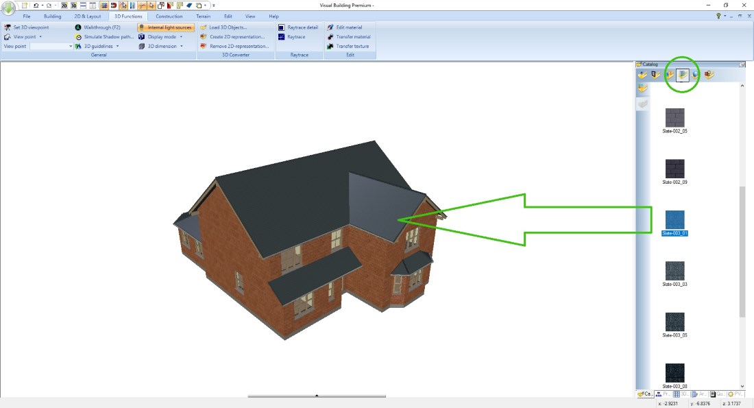
Changing roof materials, roof cladding
As usual you can simply drag and drop a texture from the catalogue onto a roof side in a 3D view.
The following video shows copying floors during the first two minutes followed by inserting and editing a roof.
Roof Construction Methods
Traditional or Cut Roof
The traditional or cut roof is essentially a roof cut and assembled on site using individual timber members.It is normally constructed using rafters and purlins. Hips and Valleys are constructed. The most common structure used is where there is a gable at both ends of the roof. The wall plates are bedded on mortar and should be lapped where they meet.
Bolted Truss Roof
Many different shaped roofs can be constructed using the bolt system. Bolted trusses were used in many domestic building prior to the trussed rafter era.
Trussed Rafter Roof
Punched metal nail plates connectors are used to connect the timbers pre delivery to site.
Roof constructions different from Visual Buildings standard construction types can be achieved using our 3D construction functions. Design one roof truss with 3D solids and then copy the entire contructions.
Visual Building Basic

Has been developed as an easy to use design and visualisation tool for self builder,extentions..
£60.00
List price
List price
£39.00
Special online offer
Special online offer
Visual Building PRO
Used by all user groups specifically to create professional plans...
£120.00
List price
List price
£99.00
Special online offer
Special online offer
Visual Building Premium
Our most powerful design and visualisation tool specifically created for ...
£180.00
List price
List price
£149.00
Special online offer
Special online offer