Create Floor Plans
This guide shows how you create floor plans using two methods, our numerical entry tools for walls and as an alternative the creation of floor plans with the help of 2D-guidelines. Both methods can be used individually for the respective use case or combined for your floor plan drawings.
With Visual Building Version 9 we have completely revised our numerical wall tools so that this article should also be of interest to users of previous versions. In addition to inserting walls, the numerical positioning of windows and doors has also been revised, which has made drawing floor plans much easier and faster.
This article will give you hints and tips on how to achieve the perfect result in the simplest and fastest way within a few minutes.
The following steps describe how your draw floor plans manually. Alternatively, you could use our project wizard to create the basic structure of your building right through to the roof in 4 easy steps, then start adding interior walls to complete your plans.
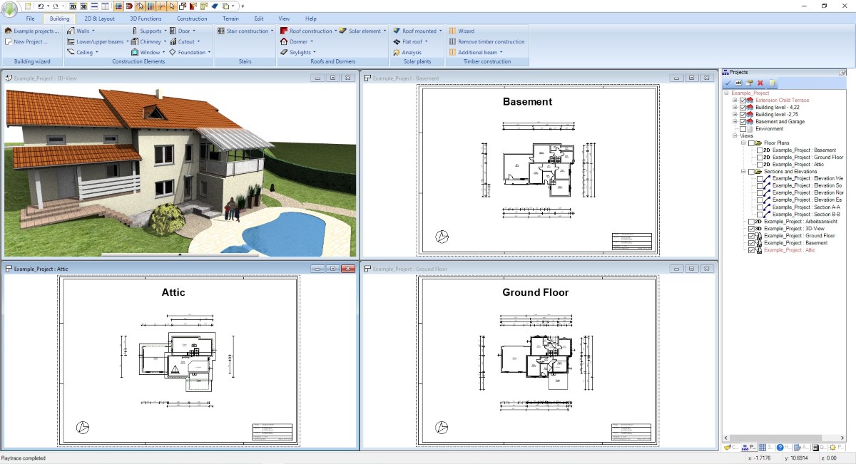
All views in Visual Building come from the internal 3D model, no matter if 2D floor plan, 2D sections or elevation views. Even if you do not need a 3D view, it still exists and when you draw walls in your floor plan everything is already in 3D. And the good thing is, it happens automatically whether you need it or not.
With Visual Building Version 9 we have completely revised our numerical wall tools so that this article should also be of interest to users of previous versions. In addition to inserting walls, the numerical positioning of windows and doors has also been revised, which has made drawing floor plans much easier and faster.
This article will give you hints and tips on how to achieve the perfect result in the simplest and fastest way within a few minutes.
The following steps describe how your draw floor plans manually. Alternatively, you could use our project wizard to create the basic structure of your building right through to the roof in 4 easy steps, then start adding interior walls to complete your plans.
All views in Visual Building come from the internal 3D model, no matter if 2D floor plan, 2D sections or elevation views. Even if you do not need a 3D view, it still exists and when you draw walls in your floor plan everything is already in 3D. And the good thing is, it happens automatically whether you need it or not.
More topics
Prepare your floor plan
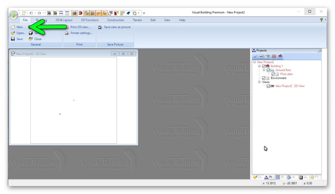
Create a new project by clicking on the New button.
The software automatically creates a structural basis of a building project, creating a new, empty 2D view and a first floor named Ground Floor.
Within each floor, a new layer named Floor Plan is created.
You can get started straight away with a few general points to avoid unnecessary input or later issues.
Tips and Advice on Floors:
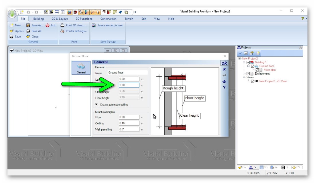
- In Visual Building walls are always as high as the rough height of the floor. Rough height is from upper edge of the ceiling below to the upper edge of your current floor ceiling.
So first change this height in our floor properties dialogue in the project viewer on the right side of the software.
All existing walls and all new ones adjust their height automatically. Standard level is 2.8 m
- Individual wall height; as just mentioned, it is rarely necessary to give walls an individual height. That would be e.g. only required if you have a lower partition in a room, or e.g. a counter in the kitchen, which is mounted on a wall.
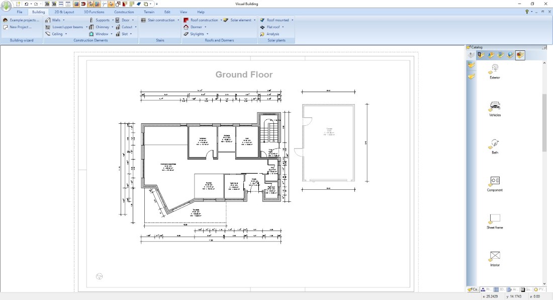
- All plans are automatically printed to scale. This scale is a property of the respective 2D view and can be changed at any time. This allows you to print plans in different scales from one 2D view.
The software automatically creates a structural basis of a building project, creating a new, empty 2D view and a first floor named Ground Floor.
Within each floor, a new layer named Floor Plan is created.
You can get started straight away with a few general points to avoid unnecessary input or later issues.
Tips and Advice on Floors:
- In Visual Building walls are always as high as the rough height of the floor. Rough height is from upper edge of the ceiling below to the upper edge of your current floor ceiling.
So first change this height in our floor properties dialogue in the project viewer on the right side of the software.
All existing walls and all new ones adjust their height automatically. Standard level is 2.8 m
- Individual wall height; as just mentioned, it is rarely necessary to give walls an individual height. That would be e.g. only required if you have a lower partition in a room, or e.g. a counter in the kitchen, which is mounted on a wall.
- All plans are automatically printed to scale. This scale is a property of the respective 2D view and can be changed at any time. This allows you to print plans in different scales from one 2D view.
Create floor plans-Tips for inserting walls
- In general, walls that run in the same direction and have the same wall thickness and other properties should be inserted as one section. Avoid splitting up these walls into separate sections, unless essential. Instead, use the lengthen / shorten wall functions on our EDIT ribbon if needed or our new numeric editing tool to change the length of a wall.
- While inserting elements in Visual Building, you can use the shortcut combination CTRL + W to change the reference point of axes the element is being placed on.
For walls this means that three available axes - center, outside and inside toggle under your cursor, so you automatically work with the correct reference side.
- To draw an exactly vertical or horizontal line, e.g. walls, dimensions, etc., you can keep the CTRL key pressed and activate the angle grid. The angle grid prevents you from making any inaccurate movements with the mouse, but only allows changing direction at an adjustable angle. Standard is 15 degrees.
- With Version 9.5 we have extended the tool dialog for numeric wall input so that you always have the above tips to hand.
Draw Floor Plan - Start with your exterior walls
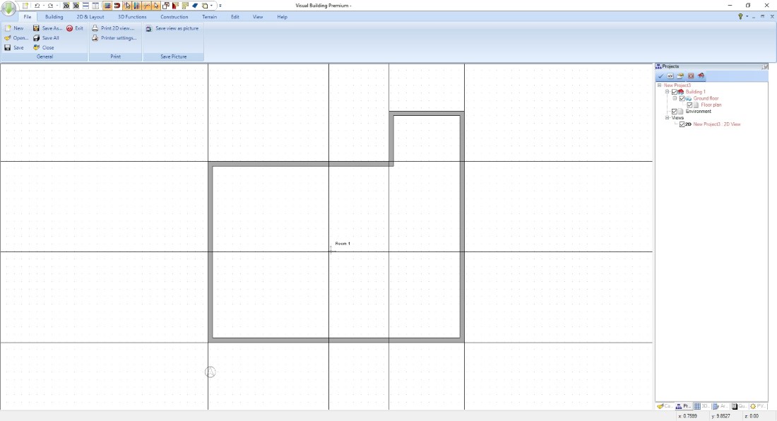
We recommend that you first draw the outer contour of your building and then complete the floor plan with interior walls. Drawing floor plans room by room could mean that walls running in the same direction are unnecessarily cut into pieces, which is not recommended for several reasons.
Walls are inserted with the following steps:
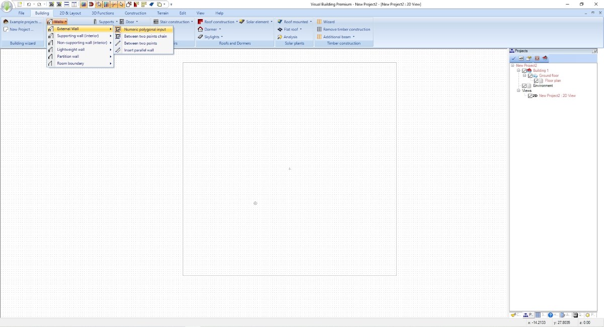
- Start the wall input tool, in this case “Exterior wall –numeric polygonal input”
- Click once with your left mouse button in your 2D view. This determines the starting point of your wall. It is not essential, where you set the first point but we recommend to do this within our 3D terrain, which shows a rectangle around the planning origin. So take this as an orientation and draw your floor plan “around” this origin. Absolute coordinates are not important.
- Click with the right mouse button and open the wall properties dialog. Adjust the wall thickness, the layer structure and, if necessary, the 2D representation of the wall. In this case that happens even before the walls have been inserted and avoids later changes.
- Close the wall dialog with OK and change the reference side of your wall with CTRL + W. As soon as the correct reference side of your wall is under your cursor, drag the wall to the direction you need.
- While dragging, you could keep the control key pressed to activate our internal angle grid. That allows you to draw accurate vertical or horizontal walls. Alternatively you can specify the correct angle numerically in our next step.
- another left mouse click opens the numeric input dialog in which you can now insert an accurate numeric value (if necessary) and the angle. Press or click enter to insert the first wall in your floor plan project
- as you have started a polygonal input tool, the last point of your previous wall is automatically the starting point of the following. So just drag the cursor to your new direction and left click to reopen the numeric dialog, insert length and angle, press enter and so on.
- Changing the reference side of a wall with CTRL+W is allowed at every stage until the numeric dialog is open.
- Changing the wall properties is only necessary once as the software keeps this setting for each wall type, exterior or interior, for your current planning session. If you want to keep your wall settings for longer, just press the “Save as default” button on the layer structure property page in our wall dialog.
The following video shows these first steps. The video uses callouts, (textual information) no music, and no other audio information.
Walls are inserted with the following steps:
- Start the wall input tool, in this case “Exterior wall –numeric polygonal input”
- Click once with your left mouse button in your 2D view. This determines the starting point of your wall. It is not essential, where you set the first point but we recommend to do this within our 3D terrain, which shows a rectangle around the planning origin. So take this as an orientation and draw your floor plan “around” this origin. Absolute coordinates are not important.
- Click with the right mouse button and open the wall properties dialog. Adjust the wall thickness, the layer structure and, if necessary, the 2D representation of the wall. In this case that happens even before the walls have been inserted and avoids later changes.
- Close the wall dialog with OK and change the reference side of your wall with CTRL + W. As soon as the correct reference side of your wall is under your cursor, drag the wall to the direction you need.
- While dragging, you could keep the control key pressed to activate our internal angle grid. That allows you to draw accurate vertical or horizontal walls. Alternatively you can specify the correct angle numerically in our next step.
- another left mouse click opens the numeric input dialog in which you can now insert an accurate numeric value (if necessary) and the angle. Press or click enter to insert the first wall in your floor plan project
- as you have started a polygonal input tool, the last point of your previous wall is automatically the starting point of the following. So just drag the cursor to your new direction and left click to reopen the numeric dialog, insert length and angle, press enter and so on.
- Changing the reference side of a wall with CTRL+W is allowed at every stage until the numeric dialog is open.
- Changing the wall properties is only necessary once as the software keeps this setting for each wall type, exterior or interior, for your current planning session. If you want to keep your wall settings for longer, just press the “Save as default” button on the layer structure property page in our wall dialog.
The following video shows these first steps. The video uses callouts, (textual information) no music, and no other audio information.
Draw Floor Plans using 2D-Guidelines
TIP: although the software has various numerical input and construction aids, the use of 2D guidelines for marking construction points, including floor plans, is common practice in CAD / architecture programs.
We mention this because it is not necessarily obvious to beginners to create an auxiliary drawing before the real construction. While this may sound like duplicate or useless work, you will quickly see the benefits of this way of working and save a lot of time. Using our numeric parallel guideline tool is especially helpful while inserting interior walls, where you typically pick distances from sides of other existing walls to determine the inner space of a room.
We mention this because it is not necessarily obvious to beginners to create an auxiliary drawing before the real construction. While this may sound like duplicate or useless work, you will quickly see the benefits of this way of working and save a lot of time. Using our numeric parallel guideline tool is especially helpful while inserting interior walls, where you typically pick distances from sides of other existing walls to determine the inner space of a room.
Create Floor Plan - Draw your interior walls
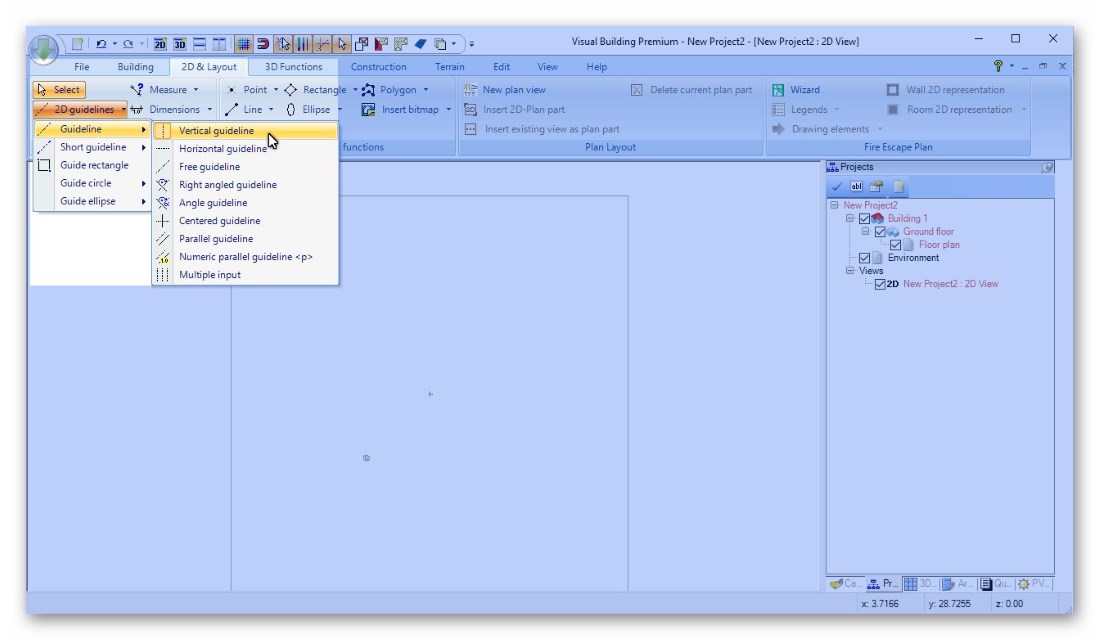
We use the numerical parallel 2D guideline, which you simply start with the P key or via the button on our 2D & Layout Ribbon.
Now move your mouse cursor over one of the existing guidelines or wall sides. When the software recognizes a line or existing edge under your cursor the guideline preview is highlighted in red. Click on the detected reference line and then move your mouse in the direction in which the new numeric guideline should be placed.
Move the mouse over one of the inner edges of the exterior wall, click and then move your cursor in the appropriate direction. Click again and enter the distance. You can now draw the first interior wall. Then use one of these newly available wall edges as reference side for the next guideline.
The working principle is always the same. Pick an existing edge, either from a guideline or an existing wall, and set the numerical distance with another guideline to enter the next element.
The following video shows these steps. The video uses callouts, (textual information) no music, and no other audio information.
Draw floor plans - Moving and extending existing walls
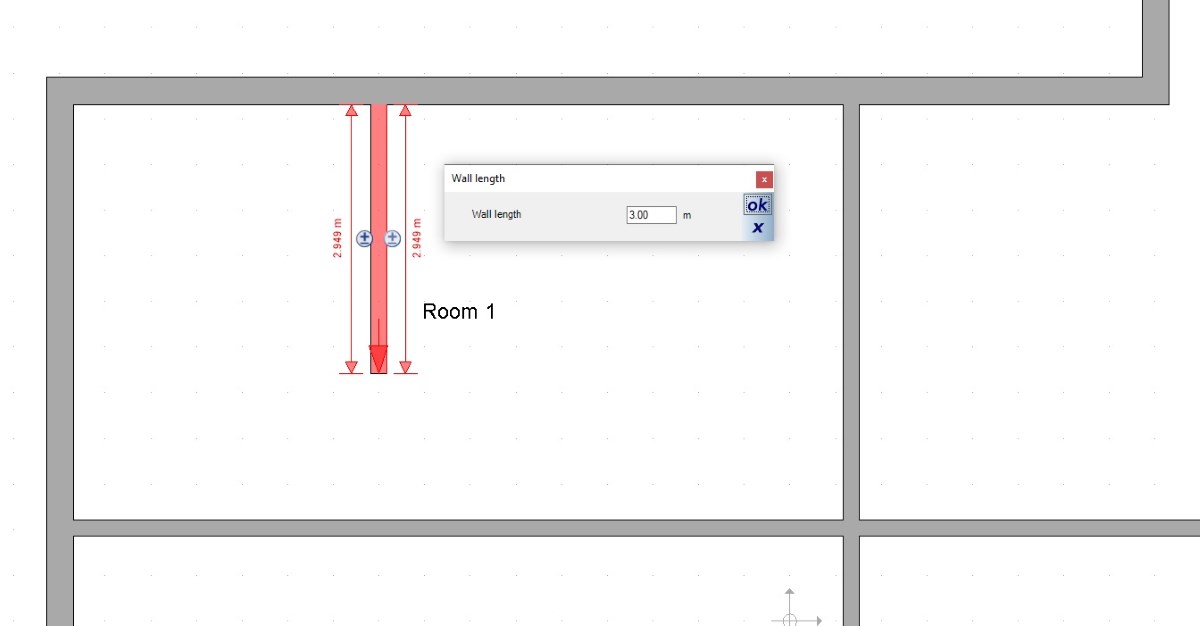
While you draw floor plans it might be necessary to move an existing wall to a new position and / to edit the length of a wall.
Changing a wall length, e.g. lengthen or shorten a wall needs a direction and therefore the length value is disabled in our wall dialog. Instead you can simply click on a wall in your floor plan and edit the length there with a numeric value. Or start the lengthen / shorten tool on our EDIT ribbon and do that with your mouse, if a numeric length is unknown or unnecessary because you only want to connect a wall to another.
Moving a wall is done with our “Move with reference point” tool, where you select a corner of your wall and then move it with you mouse to a new position.
The following video shows these tools and options.
Draw Floor Plan - Edit wall length
Create Floor Plan - Creating and labelling rooms
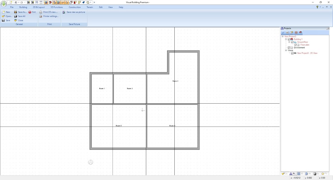
The good news is, rooms are automatically created in Visual Building while you draw your floor plan and whenever walls form a closed contour.
This process always takes place when you work on walls, enter new ones, move existing ones or lengthen / shorten them.
Labelling rooms therefore only makes sense when your floor plan has been completed, otherwise you will do unnecessary work.
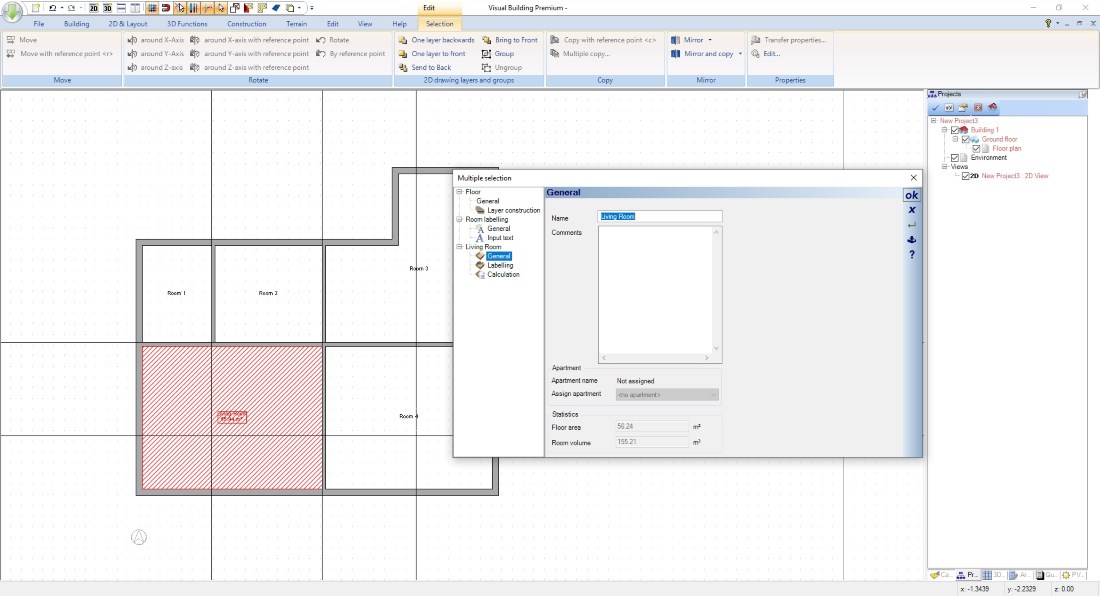
For the labelling of rooms, select the floor with a left mouse click and open the properties dialog with a following double-click or via the context menu.
Insert a name for your room, set the font size and, if necessary, select one of the automatic area calculation values which is then added as text to your floor plan.
You can also transfer the text style and calculation with "Transfer properties" from the context menu to all other rooms in your floor plan.
This process always takes place when you work on walls, enter new ones, move existing ones or lengthen / shorten them.
Labelling rooms therefore only makes sense when your floor plan has been completed, otherwise you will do unnecessary work.
For the labelling of rooms, select the floor with a left mouse click and open the properties dialog with a following double-click or via the context menu.
Insert a name for your room, set the font size and, if necessary, select one of the automatic area calculation values which is then added as text to your floor plan.
You can also transfer the text style and calculation with "Transfer properties" from the context menu to all other rooms in your floor plan.
See other building plan options in Visual Building or go back to the main page.
Create Floor Plan - Create Rooms
Visual Building Basic

Has been developed as an easy to use design and visualisation tool for self builder,extentions..
£60.00
List price
List price
£39.00
Special online offer
Special online offer
Visual Building PRO
Used by all user groups specifically to create professional plans...
£120.00
List price
List price
£99.00
Special online offer
Special online offer
Visual Building Premium
Our most powerful design and visualisation tool specifically created for ...
£180.00
List price
List price
£149.00
Special online offer
Special online offer