• This email address is being protected from spambots. You need JavaScript enabled to view it.
×

Notice

The forum is in read only mode.

Welcome, Guest
Username: Password: Remember me
31 Aug 2022
Our new version 11.0.11.0 is now available.
Read More...
  • Page:
  • 1

TOPIC:

Domestic Electrical Circuits 26 Sep 2014 17:56 #1704

The symbols were drawn using the 2D tools, but once you have created such a symbol you can save it to your symbol library to use again. There is a set of electrical symbols in the catalogue, but these do not show terminal connections. Your need is more detail than most CAD users require. I think the above demo was created for an educational user, teaching domestic wiring.

Domestic Electrical Circuits 26 Sep 2014 17:52 #1703

  • Amie Merten
  • Amie Merten's Avatar Topic Author
  • Offline
  • Posts: 8
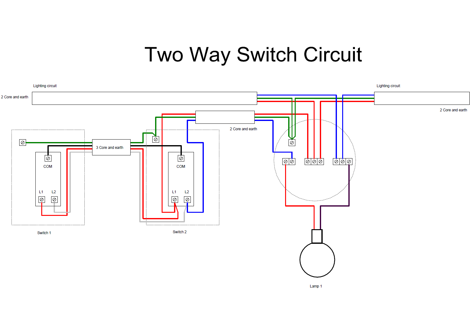
Thank you - thats exactly the level of detail that I need. Are the switch and ceiling rose symbols showing the terminal connections standard symbols?

Domestic Electrical Circuits 26 Sep 2014 17:41 #1702

You can achieve this in either Visual Building or Visual Floor Planner. If you are creating your own symbols to show terminal connections then Visual Building is the better solution.

Here is an example domestic circuit created using Visual Building.

Click to zoom

Domestic Electrical Circuits 26 Sep 2014 17:32 #1701

  • Amie Merten
  • Amie Merten's Avatar Topic Author
  • Offline
  • Posts: 8
I am a Visual Building user. I now want to draw some simple domestic circuits. Im mapping out an existing circuit and need to show individual sockect connections.

I see Visual Building has electrical symbols, but I need to show individual terminal connections which is more detail than most CAD symbols show.

Is Visual Building an overkill for such a task or could I achieve the same with your Visual Floor Planner?
  • Page:
  • 1
Time to create page: 0.092 seconds