What’s new in Visual Building 9.5 :
An overview of the new features in our Visual Building versions 9.5 .
As always, we have added features and content that we have filtered out of the suggestions and wishes of the users. And we have revised existing tools for inserting and editing walls, windows and doors in order to improve our floor plan functions and to make the handling much easier and faster.
Main new features:
- New and improved numeric polygonal wall construction function
- New and improved tools to position windows, doors and wall openings numerically
- Groups, alias Mini-Projects
- New Group Catalog with 250 new Groups
- Saving your own groups to the catalog
- Changes to the catalog for 3D Objects, Textures, Materials, 2D-Symbols and Groups. Create and access your own catalog folders.
- Additional Components for Window Constructions, Windows and Doors. Lintels and roller shutters, fixtures (handles for window constructions), surroundings for windows and doors
- Height dimensions with alternative values above sea level in section and elevation views
- More than 1.250 new 3D objects in our standard catalogs
- New Help PlugIn in our toolbox with direct links to videos and help topics
- ...
Details
New and improved tools for inserting and editing walls
With version 9.5 we have revised our numeric polygonal input tools for walls. The numeric tools now show dimension lines during input once you have set the starting point of your wall and open a new dialog on the second mouse click (which normally inserts a wall in your project). Now it opens a dialog in which you can edit the numeric lenght and angle of your wall completed with ENTER, either with a click on the dialog button or by just pressing enter on your keyboard.
Inserting walls is now much easier and faster, two mouse clicks + enter do the job. These tools are designed as polygonal input variants, what means the end point of your previous wall automatically becomes the starting point of the following.
That allows you to insert multiple walls, your building outline for example, in a combined process. The dialog also shows a section with some reminders such as "keep the CTRL key pressed to insert accurate vertical or horizontal walls, use CTRL+W to toggle the active wall side when you have set the first point,....
There are only 3 handling advices for walls you should keep in mind.
When you select a wall, two dimension lines with numeric edit buttons appear and allow changing the length of the selected element. An arrow on the wall center line indicates in which direction the new length will apply. If necessary, you can change the current wall direction directly in your right mouse button context menu.
New and improved tools for positioning windows, doors and wall openings numerically
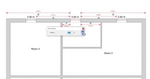
With version 9.5 selected windows, doors and wall openings show a set of dimension lines including numeric editor buttons to edit a distance very quickly.
The number of dimension lines depends on the position of the window itself and the current geometry situation of walls.
So that you always have all necessary options to edit the value you need or the one you can easily pick out of your existing floor plans. All previous steps in older Visual Building versions to position a window with a numeric distance to a certain point are still available but more or less obsolete and replaced by just a mouse click + enter, what significantly speeds the drawing of floor plans up. Just insert a window via drag and drop in your target wall without taking care of the correct position.
Select it with a left mouse click, edit the numeric value you need and press enter.
Groups, alias Mini-Projects
Contrary to what is likely expected, groups are not just a combination of already existing 3D objects from the catalog, but mini-projects that can contain almost all constructive elements, but of course also combined with 3D objects.
Groups are inserted in your project as usual via drag and drop from the catalog.
And you can easily add your own new groups in the catalog by selecting various elements with a mouse frame and saving them as a group via the right mouse button context menu.
The special thing about it is that groups can be separated into their previous elements once added to your current project. That means walls, roofs, 3D constructions, etc., simply all parts of a group become the original elements again and can be edited and changed as usual.
With this function, you can save all components of a planning, whether it be a garage, balcony, kitchenette, seating groups, or even completely furnished rooms to the catalog and use them in future projects, simply by drag and drop.
New Group Catalog
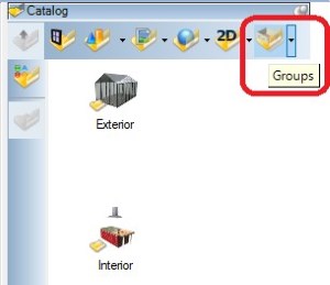
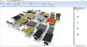
We have provided a separate category for groups in our catalog.
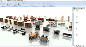
In this catalog we have already added numerous sample groups (approx. 250), partly to show the various options, but also very practical examples that cannot be used as simple 3D objects, e.g. Garages, carports, saunas, garden houses etc..
Some examples for the interior, fireplaces, kitchenettes and kitchen islands, bathrooms, saunas, seating groups, etc..
Saving your own groups to the catalog
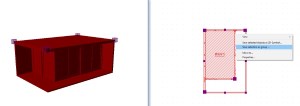
To save a group, you must select the components together, which is usually easiest by dragging a frame in a 2D view, simply by keeping the left mouse button pressed. Just as you may be used to saving 2D symbols.
With the context menu of the right mouse button you get the option "Save selection as group ...".
It is important to understand that you only get this context menu in an active 2D view. So even if you select elements in a 3D or sectional view, you have to activate a 2D top view afterwards.
The reason is that exactly the current 2D representation of the active view is saved as a 2D symbol to the group and later also serves as a 2D replacement representation for inserted groups.
As a result groups in your floor plans look exactly as if they were part of the drawing and not, as with 3D objects, from a calculated representation of the surface of the 3D model.
Changes to the catalog for 3D Objects, Textures, Materials, 2D-Symbols and Groups
So far, the catalogs for 3D objects, textures, materials, 2D symbols and recently also for groups only pointed to specified main directories in your installation path. Loading and managing your own files in your own directories was a bit complicated and only possible via a "Open file ..." dialog.
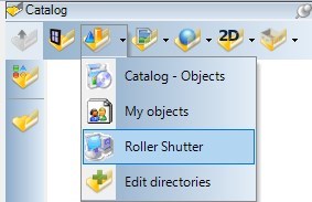
Now you can integrate separate directories for each category and then navigate within these directories as usual in your catalog.
Both, the buttons for the main categories and the dialog for managing the directories have been revised.
The buttons now offer a menu via the small black arrow on the right-hand side, which contains the previous main directories, the standard alternative in your user directory as "My Objects" and an entry for opening the directory dialog. If you define your own directories, these are added as additional menu entries. With one click on the menu entry, the catalog display changes to this directory.
If you click directly on the button the catalog behaves as before and switches between the main categories.
Additional Components for Window Constructions, Windows and Doors
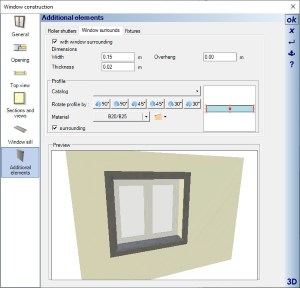
You can activate additional elements for the mentioned elements within the property dialog. These include roller shutters and lintels, window surrounds and fixtures (handles).
Depending on the element, certain options are disabled in the dialog, so the option fixtures for doors and windows from 3D objects is not available because both, doors and windows consist of finished 3D objects and fixtures are or should be included there. Fixtures are only available for window constructions.
Depending on the element, certain options are disabled in the dialog, so the option fixtures for doors and windows from 3D objects is not available because both, doors and windows consist of finished 3D objects and fixtures are or should be included there. Fixtures are only available for window constructions.
Lintels and roller shutters
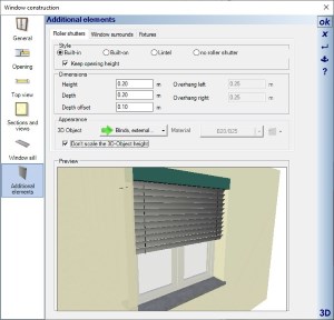
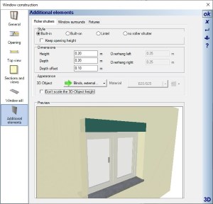
You can activate various roller shutter designs and lintels on the roller shutter property page.
Lintels are internally generated by the software based on the dimensions, roller shutters are loaded and scaled from finished 3D objects in our catalog.
The option "Keep opening height" determines whether the window height should be decreased by the height of the roller shutter or the window height remains and the roller shutter above increases the wall opening.
The software already contains an extensive catalog of 3D objects for the various roller shutter designs. Including those in which the slats are visible at different heights.
Fixtures (handles for window constructions)
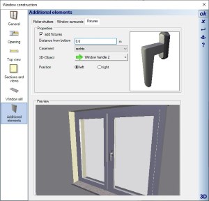
Window handles can only be used with window constructions. The handle objects themselves are normal 3D objects from the catalog. You could therefore use your own 3D Object variants, you just have to take into account that the 3D objects are rotated in the same way as shown in our example.
With the distance from below you position the object vertically. The horizontal alignment is centered on the frame profile of the active window sash.
The list of sashes is based on the structure of the window construction itself and the position determines whether the handle is placed on the left or right of the active sash.
Window surrounds (surroundings for windows and doors)
Window surrounds are created exactly like the sweep solids of our 3D construction PlugIn and automatically follow the opening polygon. By default, a rectangular profile is specified here, but you can also use other profiles from the profiles catalog or add your own. The behaviour and the profile options correspond to those of sweep solids.
With active option “surrounding”, the window or door is completely surrounded. Without this option, the lower part of the polygon remains free, which you need for doors or floor-to-ceiling windows.
With active option “surrounding”, the window or door is completely surrounded. Without this option, the lower part of the polygon remains free, which you need for doors or floor-to-ceiling windows.
Height dimensions with alternative values above sea level in section and elevation views
Height dimensions in 2D-section views and elevations have always referred to the zero level of your planning. And it remains that way. However, you can now specify an internal value that is added to this building level, an internal height above sea level.
You can enter the value in two ways, first in the dialog of the terrain and in your ENVIRONMENT layer properties dialog in our Project Viewer.
You can enter the value in two ways, first in the dialog of the terrain and in your ENVIRONMENT layer properties dialog in our Project Viewer.
More than 1.250 new 3D objects in our standard catalogs
With version 9 we have added more than 1,250 3D objects in our standard catalog.
250 new Groups in our new Group catalog
Garden homes, Garages in different designs,Carports, single and double carports in different designs, pavilions, awnings, fireplaces, Greenhouses
Finished fitted kitchens / kitchenettes, kitchen islands, saunas, seating groups, Bathroom combinations, ....
Finished fitted kitchens / kitchenettes, kitchen islands, saunas, seating groups, Bathroom combinations, ....
New Help PlugIn in our toolbox
These functions have been implemented especially for new users.
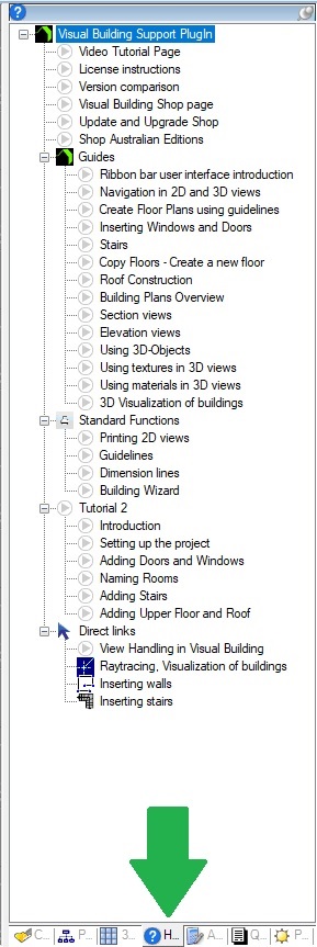
The new HTML help plug-in is located in the general toolbox, where the catalogs and the project viewer can also be found.
The help topics are structured in a tree view within the toolbox and can be called up by double-clicking or via the context menu of the right mouse button.
Questions? If you have a question about our products please email customercare@visualbuilding.co.uk


